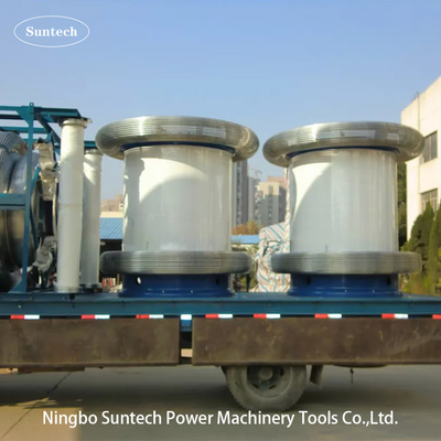
PD Free AC Resonant Test Systems , No Corona Induced Withstand Voltage Test Sets
I. Product Description:
Induced voltage withstand test(IVWT), also called induced overvoltage withstand test ,ACSD,ACLD, DVDF, is one of most important dielectric test of power transformers.As per IEC60076-3-2013, IVWT is necessary routine test and acceptance test ater installation for abobe 110KV Power transformer .
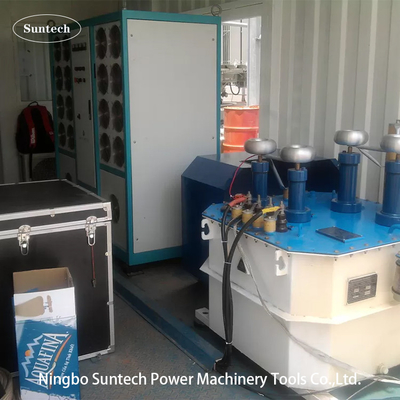
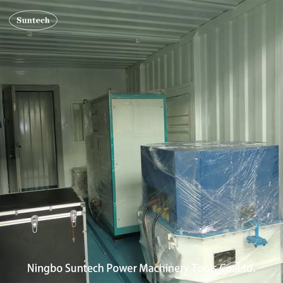
The FKWJF-300 Non Partial Discharge Variable Frequency Power Serial Connected ResonanceTest System is composed of non partial discharge variable frequency power, step-up transformer, compensation reactor and capacitive voltage divider. The transformer partial discharges, induced withstand voltage test system performs the test in the way of induction. It applied voltage to the LV side of the test object and produced the large excitation current via changing the frequency of the test circuit with the application of parallel resonance principle. The Serial Connected Resonance Test System is made up of variable frequency power source, excitation transformer, HV reactor and capacitive voltage divider. The capacitor and reactor of test object formed a serial resonance connection. The voltage divider is in serial connection with the test object and used for measuring the resonance voltage and acting as the overvoltage protection signal. The frequency modulation power
output is coupled to series resonance circuit via excitation transformer to provide the exciting power. This test system does not have a problem of large starting current. The power supply with small capacity is capable of fulfilling the test equivalent to 30 to 60 times of the power supply. This greatly solved the problem of poor capacity of test power at site.
FKWJF 300KW systems can provide single phase +35KV /150Hz~200Hz alternative current to test up to 630 MVA/220 kV power transformers insulation performance between turns of coils, layer to layer. i.e, minor insulation, including uniform and non-uniform insulation.
Together 2 or 4 channels PD analyzer and its accessories, Model FKWJF400KW also can be used for Induced voltage test with partial discharge measurement (IVPD). Together HV test reactor group, HV divider and its accessories, it also can perform AC applied withstand voltage test thorugh LC resonant circuit within 20~300Hz.
II. Main features
- The device is safe and reliable, which integrated all kinds of protections including overvoltage protection, overcurrent protection, discharge (breakdown) protection, protection after test power failed, zero voltage start protection, overheat protection, etc. When any one of the above
- protections acted, the device will block the test voltage output and switch off the power of main circuit to make sure the safety of test personnel, test object and the test system.
- The operation is easy and convenient with simple connection.
- Small in size, light in weight, flexible handling which is suitable for field use.
- It adopts microcomputer control, which has good output stability and high reliability.
- The high voltgae output sine wave distortion is less than 1%, which has no damage to the test object.
III. Test Guideline

Note : The above figure is connection circuit for induced withstand voltage test and PD detecting to power transformer
During the PD test and inductive voltage withstand test, the tested transformer is similar to a large capacitive test object. The capacitive reactive current of the transformer is compensated by the inductive current of the compensating reactor.The variable frequency power supply provides the whole system with active loss and small part of reactive loss. And both losses satisfy the no-load loss of electric transformer at test frequency.The voltage divider is installed at the HV output terminal of the excitation transformer. Measure the voltage at LV (low voltage) side of the main transformer by a peak voltmeter and calculate the voltage at the HV side according to voltage ratio of the main transformer.
The bushing capacitance of the main transformer is used as the coupling capacitor. Input partial discharge signal to the PD tester to measure the PD value.

Note: The above figure is connection circuit for AC applied withstand voltage with LC resonant principle.
IV. Main Components
| Item |
Product Name |
Type and specification |
Quantity |
Remarks |
| 1 |
PD free variable frequency power supply |
FKWJF-300kW |
1 piece |
|
| 2 |
PD free excitation transformer |
CQSB(J)-300kVA |
1 piece |
|
| 3 |
PD free compensating reactor |
CHX(kf)-600kVA/22kV |
2 pieces |
For Induced test |
| 4 |
PD free capacitive voltage divider |
TRF-50kV/300pF |
1 set |
For PD sampling |
| 5 |
HV test reactor |
CHX(kf)-500kVA/200kV |
2 pieces |
For resonance voltage withstand |
| 6 |
HV capacitance voltage divider |
TRF-400kV-2500pF |
1 set |
For resonance voltage sampling |
| 7 |
Corona ring for PD test to main power transformer |
220KV |
3 pieces |
For PD testing |
Note: the above table is just for example
V. General Technical data:
1.Service conditions
- Altitude above sea level ≤ 1000m
- Ambient temperature: -10℃~45℃
- Relative humidity≤90%RH(at20℃)
- Using locations: indoors and outdoors
- No corrosive metal or insulation air existing around the system
- Install and place it at flat position. Installation tilt≤5°
- With one reliable ground point. Ground resistance<0.5Ω
2. Technical specification
- Rated input power supply:380V±10%, three phase, 50Hz
- Rated output power of variable frequency power supply: 300Kw
- Rated output capacity: 1000kVA( at resonant voltage withstand test);
- 1200kVA( at PD free inductive voltage withstand compensation state)
- Max. output voltage: 400kV or OEM
- Output phase: single phase
- Variable frequency range: 20Hz~400Hz, frequency adjustable within this range
- Output frequency resolution: 0.01Hz
- Output frequency instability ≤0.1%
- Sinusoidal wave output voltage. Waveform distortion factor≤1.0%
- PD level of test system itself≤10pC
- Operation time: 90 min for transformer PD test and 60min for resonant voltage withstand test
- Insulation level: 1 min at 110% rated voltage
VI.Accessories
- Accessory box for storage accessoires
- Input cables of power source
- Output cables of power source
- Output cables of exciting transformer
- System grounding cables
- Parallel cables of the reactor
- HV measuring cables ( the signal output cables of voltage divider )
- HV output cables(reactor to divide,divider to test object)
- Supporting base for divider
- Corona ring for test reactor and divider
- A final test report, a quality Certificate ,a user manual and a packing list are offered .
VII. Other typical model
1 Optional model for Induced withstand voltage test
| System Model |
Output power |
Max Application |
| FKWJF-150KW |
150KW |
66KV power transformer |
| FKWJF-200KW |
200KW |
110KV power transformer |
| FKWJF-300KW |
300KW |
220KV/630MW and below power transformer |
| FKWJF-400KW |
400KW |
220KV/above 630MW power transformer |
Special requirement can be made by order
|

 Your message must be between 20-3,000 characters!
 Please check your E-mail!
  Your message must be between 20-3,000 characters!
 Please check your E-mail!
